
What Is Cable Connector Overmolding?
Understand cable connector overmolding, cable routing, strain relief, mold access, and why open access can affect vertical molding machine selection.
2026-07-11 | 8 min read | Category: Application-related Concepts
Quick Answer
Cable connector overmolding molds plastic or soft material around a cable, terminal, connector, or wire assembly to create insulation, strain relief, shape, or protection.
Why do cable and connector projects often require extra attention to mold access? Start with the workflow, not only the machine name. The term helps a project team discuss the part, material, mold, loading method, removal method, and production target with the same meaning.
Use this page as a concept reference, not as a final machine specification, mold design rule, or processing parameter recommendation.
What Cable Connector Overmolding Means in a Molding Project
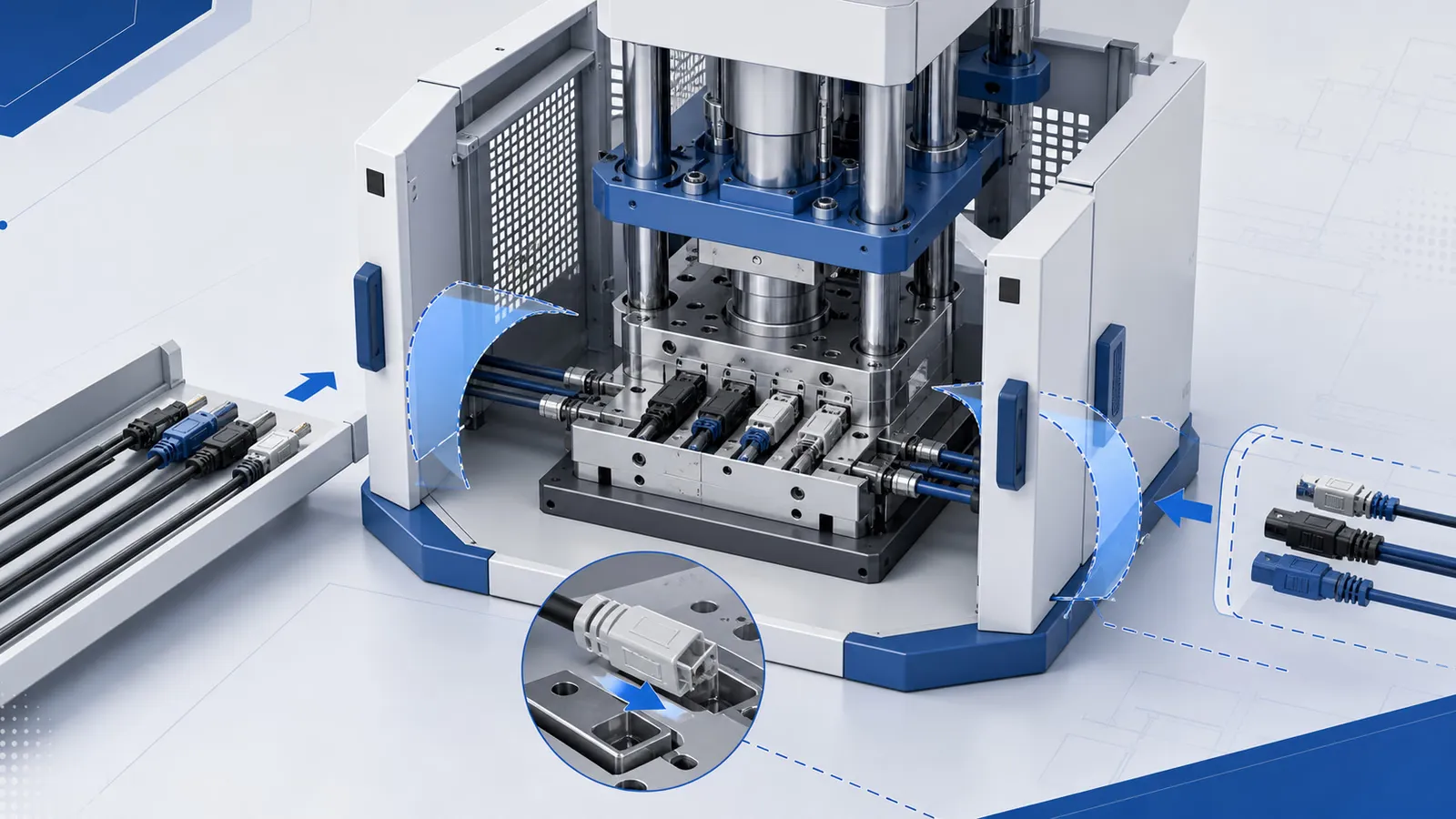
Cable connector overmolding is not only about filling a cavity. The cable may extend outside the mold. Terminals may need orientation checks. The cable may need to be routed, supported, or protected before mold close. If tie-bars, guards, or machine layout block the cable path, the operator may lose time or create inconsistent placement. The strain relief area and finished connector appearance also depend on the mold, material, and loading method working together.
For cable connector projects, the term is useful only when it leads to practical review questions: how the cable is routed, how terminals are held, where material enters, how much mold access is needed, and how the finished connector is removed without damaging the cable or insert.
Why It Matters for Machine Selection
Machine review should connect cable length, connector shape, terminal positioning, mold access, injection direction, table movement, and whether the project stays manual or later moves toward automation.
| Review point | Why it matters |
|---|---|
| Cable routing | Determines whether front access is enough or side/open access is required. |
| Terminal positioning | Requires stable seating and visual checking before mold close. |
| Strain relief shape | Connects product design, material flow, and mold layout. |
| Loading time | Cable handling can be slower than loading rigid inserts. |
How to Compare Related Options
The best option depends on the actual part and production method. Use the comparison below as a review map, then confirm the project details with drawings, samples, material information, and mold concept.
| Concept | Practical meaning |
|---|---|
| Short connector insert | May fit a simple loading layout if routing is limited. |
| Long cable assembly | Often needs side clearance and support outside the mold. |
| Multi-cavity cable mold | Increases loading checks and routing complexity. |
| Automation-ready cable project | Requires careful feeding, orientation, cable management, and guarding. |
What to Check Before Requesting a Recommendation
Before asking Deboge to recommend a machine structure, collect the information that explains the real production task. Clear project evidence is more useful than a broad keyword.
| Review point | Why it matters |
|---|---|
| Cable and connector sample | Shows cable length, stiffness, terminal position, and overmolded area. |
| Mold or fixture concept | Shows how the cable is held and routed before injection. |
| Material information | PVC, TPE, TPU, or other material family if known. |
| Quality concerns | Flash, short shot, cable exposure, terminal shift, strain relief cracking, or appearance defects. |
Common Mistakes to Avoid
- Ignoring the cable section outside the cavity.
- Treating strain relief defects as only material problems.
- Choosing a machine before checking cable routing and side access.
- Planning automation without proving that cables can be fed and oriented reliably.
How This Connects to Other Resource Pages
Knowledge Base pages explain the concept. Machine pages show available machine structure directions. Guides help compare options when a project is closer to inquiry. Troubleshooting and material pages help when an existing process already has symptoms.
FAQ
Why is cable routing important in machine selection?
The cable may extend outside the mold and need side clearance, support, and repeatable placement before mold close.
Can cable connector overmolding use fixed platen machines?
Sometimes, if routing, loading, and removal are simple. More complex cable paths may require slide table or open access review.
What defects are common in cable overmolding discussions?
Common discussion points include flash, short shot, exposed wire or terminal, strain relief cracking, bubbles, and appearance problems.
What should be prepared for inquiry?
Send cable and connector samples or drawings, material information, mold concept, routing method, target output, and defect photos if available.
Related Reading
Need technical information specific to your application?
Deboge engineering can answer your machine structure, configuration, and process questions directly.