
Cable Connector Overmolding Machine Selection Guide
Select a vertical molding machine for cable connector overmolding by reviewing cable routing, side access, strain relief, fixtures, mold access, and injection structure.
2026-07-11 | 9 min read | Category: Choose by Application
Cable connector overmolding is often limited by access and handling rather than by a simple machine size question. Cables must be routed, supported, protected, and removed without stressing the assembly.
This guide focuses on cable routing, strain relief, side access, fixture design, table configuration, and injection structure. It helps prepare a technical discussion before a specific machine recommendation is made.
Quick Answer
For cable connector overmolding, review cable length, routing direction, connector geometry, fixture support, mold access, gate concept, side access, and removal method. Tie-bar-less clamping or horizontal injection may be reviewed when the cable and mold layout require it.
When This Guide Is Most Useful
Use this guide for connector bodies, cable ends, wire harness components, power plug and cord products, and electrical overmolding projects where cable handling affects machine selection.
Selection Path
Map the cable route
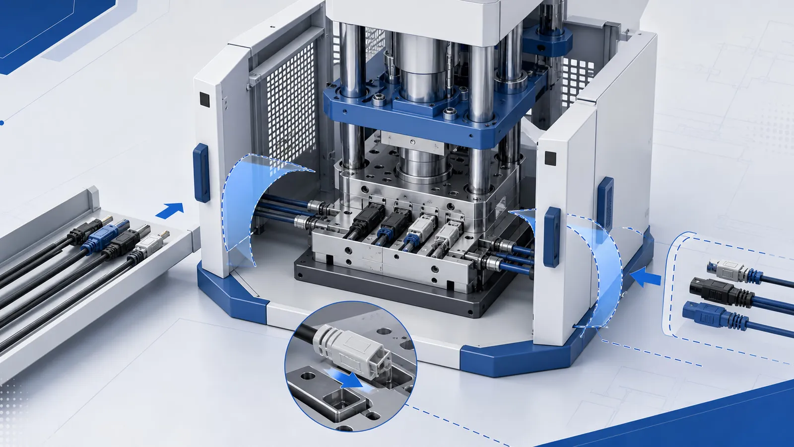
Show where the cable enters the mold area, how it is supported, and where excess cable length will sit during loading and molding. Cable route can determine whether open side access is important.
Review fixture and strain relief support
The cable and connector must be held without pulling, twisting, or shifting. Fixture design and access direction can affect table choice and machine structure.
Check injection direction and gate concept
Gate layout, connector geometry, and material flow may influence whether vertical injection or horizontal injection should be discussed. This must be tied to the mold concept, not assumed from the application name.
Plan removal and cable handling after molding
After molding, the part may still be connected to a long cable or harness. Removal and collection should be planned before the machine and table are confirmed.
Decision Points to Review
| Review point | Why it matters | What to prepare |
|---|---|---|
| Cable routing | Cables need physical space and a predictable path during loading. | Cable length, stiffness, bend radius concerns, and route photos. |
| Side access | Tie-bars or machine frame may limit cable approach and fixture movement. | Access direction, fixture size, and operator or robot path. |
| Mold and gate concept | Connector geometry and material entry affect injection structure review. | Mold layout, gate assumptions, and part drawings. |
| Removal and collection | Cable assemblies can be awkward to unload or collect. | Removal direction, collection tray, and post-molding handling plan. |
How to Compare Common Options
| Option | When it may fit | What to verify |
|---|---|---|
| Slide table | Cable loading is easier when the lower mold area moves outward. | Cable support during table movement and loading position. |
| Tie-bar-less clamping | Cables, fixtures, or robots need open side access. | Whether side access is a real constraint. |
| Vertical clamping with horizontal injection | The mold or gate concept points toward side injection. | Gate layout, injection unit position, and mold clearance. |
Information to Prepare Before Asking for a Recommendation
| Information | Why Deboge needs it |
|---|---|
| Cable and connector drawings | They show routing, molded area, and strain relief needs. |
| Cable sample photos | Real cable stiffness and length affect access review. |
| Mold concept | Gate direction and fixture space affect machine structure. |
| Handling plan | Loading and removal steps determine table and automation discussion. |
Common Mistakes to Avoid
- Treating cable connector overmolding as a generic insert molding project.
- Forgetting to show where cable length will go during loading.
- Choosing a machine before gate direction and cable route are reviewed.
- Ignoring part collection after molded cable assemblies are removed.
How This Guide Connects to Other Resources
Use this guide with the mold access and tie-bar-less clamping knowledge pages. For power plug or cord products, review the related application page. If automation may be added later, use the automation-ready guide.
Related Reading
- Cable and Connector Overmolding
- Tie-bar-less Vertical Clamping
- Mold Access
- Automation-ready Machine Selection Guide
FAQ
Why does cable routing matter for machine selection?
Cable routing affects side access, fixture movement, table choice, and part removal. Long or stiff cables may need more open access around the mold.
Does cable connector overmolding always require tie-bar-less clamping?
No. Tie-bar-less clamping should be reviewed when tie-bars limit cable routing, fixture movement, or automation access.
When should horizontal injection be reviewed for connector projects?
Review horizontal injection when the mold and gate concept, shot requirement, or connector geometry makes side injection worth discussing.
What should be sent for cable connector overmolding review?
Send cable and connector drawings, cable samples or photos, material information, mold concept, cable routing notes, and loading and removal workflow.
Related Reading
Ready to confirm a machine selection?
Send your product details, mold specs, and production requirements. Deboge engineering will review and recommend a specific configuration.