
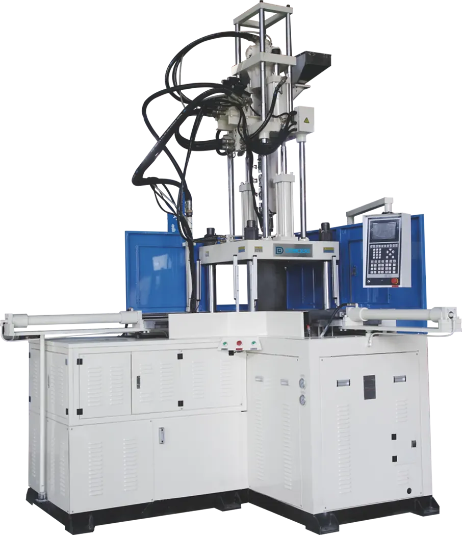
Snow Sweeper Wafer Brush Insert Molding with DA-1200LS
See how DA-1200LS produces snow sweeper wafer brushes for a Russian customer, with manual brush insert loading, one cavity and an approximately 25-second cycle.
2026-10-14 | 5 min read | Industry: Road cleaning and snow removal equipment
In manual insert molding, the operator’s route between loading and unloading positions can affect the rhythm of every production cycle. This project for a customer in Russia uses a DEBOGE DA-1200LS vertical injection molding machine to produce snow sweeper wafer brushes for road cleaning and snow removal equipment.
The configuration combines manual loading of brush inserts, a single-cavity mold and a reported cycle of approximately 25 seconds. Depending on the brush design, the inserts can be polypropylene (PP) bristles, steel wires, or a combination of both. Its right-angle handling layout was selected to reduce the operator movement required between insert placement and product removal.
The wafer brush and its application
A snow sweeper wafer brush is a working component assembled onto rotating sweeping equipment. The supplied product photograph shows its circular form and radial bristle arrangement. For this application, the production process must accommodate the brush inserts and their placement in the mold.
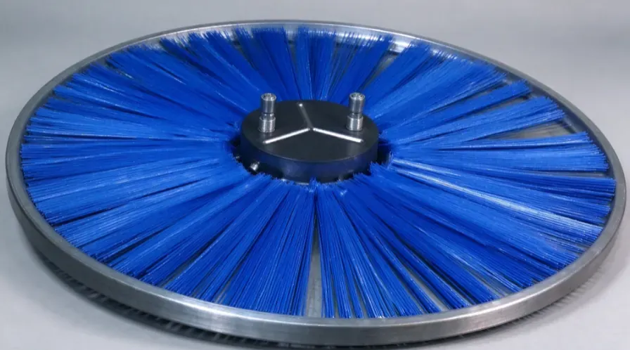
The project uses insert molding: the brush inserts are positioned in the tool before plastic is injected. The insert location, molded geometry and access for handling therefore need to be considered together when configuring the production cell.
| Item | Configuration in this project |
|---|---|
| Product | Snow sweeper wafer brush |
| Customer region | Russia |
| End application | Road cleaning and snow removal equipment |
| Machine | DA-1200LS vertical injection molding machine |
| Handling layout | Right-angle arrangement |
| Process | Brush insert molding |
| Brush material options | Polypropylene (PP), steel wires, or a combination of both, depending on the brush design |
| Insert loading | Manual loading of brush inserts |
| Mold cavities | 1 |
| Reported cycle time | Approximately 25 seconds |
| Main production objective | Reduce unnecessary operator movement and improve production rhythm |
The reported cycle applies to this product and configuration. Another brush design, material combination, mold or handling arrangement requires its own cycle assessment.
Why the right-angle handling layout was selected
The customer’s process depends on an operator repeatedly placing inserts and removing molded products. Machine selection therefore needed to account for where those tasks take place, alongside the molding requirements.
In the double-slide arrangement described for this project, the operator would move left and right between two working positions. The DA-1200LS right-angle layout allows the operator to work within a smaller area and turn between the loading and unloading tasks. The practical benefit is a shorter route through the repeated handling sequence.
Here, right-angle describes the handling layout. The DA-1200LS retains vertical clamping and vertical injection. These features and the working positions serve different purposes: the vertical mold arrangement provides access for insert placement, while the handling layout determines how the operator moves between tasks.
This is a layout choice for the documented application. When comparing slide-table machine arrangements for a new part, the relevant questions include the size of the part, the operator’s reach, the location of incoming inserts and the collection point for molded products.
What to review in the manual insert molding process
Insert location and access to the tool
Manual loading makes the relationship between the insert, mold and operator especially important. For a comparable project, the tooling review should establish how each insert is supported and located, how the operator places it and how the molded assembly can be removed without obstructing the next loading operation.
The part and insert drawings should identify the required molded areas and the surfaces that must remain exposed. Photographs are useful for understanding the overall arrangement, but they do not replace these dimensional requirements.
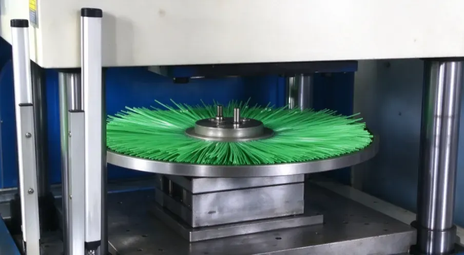
The complete handling sequence
A useful layout review follows the operator through an entire cycle: collect the next inserts, place them in the tool, remove the molded product when the machine permits access, and transfer it to the collection area. The order and timing must match the actual machine sequence.
For this project, the source identifies reduced movement between working positions as the reason for selecting the right-angle arrangement. For another installation, the insert supply and finished-part collection positions should be included in the review; changing those positions can change the benefit of a particular machine layout.
Product-specific materials and acceptance requirements
Specify the brush insert material—polypropylene bristles, steel wires, or a combination—and the brush assembly dimensions for a new project assessment. The resin to be injected should be specified separately: the brush material and the molding resin have different roles in the process. These inputs influence tooling and process decisions and should be supplied with the production target.
Because the finished brush operates as part of rotating equipment, the customer should also define the dimensional and functional acceptance requirements for that assembly. Those requirements belong in the part specification and validation plan. A molding cycle time alone does not establish performance in service.
Reported project outcome
Reported results from this project include easier management of manual insert loading, reduced operator movement and a steadier production rhythm after adopting the DA-1200LS. These are qualitative results from the documented installation; no measured percentage improvement is reported.
The central lesson is that insert molding machine selection includes the work carried out around the mold. In this case, a single-cavity tool and an approximately 25-second reported cycle were paired with a layout chosen for repeated manual handling.
Common questions
What machine was used for the snow sweeper wafer brush?
The project uses a DEBOGE DA-1200LS vertical injection molding machine with a right-angle handling layout. The customer is located in Russia.
Are the brush inserts loaded automatically?
No. The documented process uses manual loading of brush inserts. Depending on the brush design, these can be polypropylene bristles, steel wires, or a combination of both. The layout was selected to make the operator’s repeated loading and removal tasks easier to manage.
What are the cavity count and cycle time?
The mold has one cavity, and the reported project cycle is approximately 25 seconds. These values describe this production setup and are not a cycle guarantee for other brush designs.
What needs to be checked for a different wafer brush?
Review the finished-part and insert drawings, brush material, intended molding resin, assembly dimensions and handling requirements. These inputs help establish the tooling and working layout for that particular product.
Discuss your wafer brush molding project
Send DEBOGE your finished-part drawing or sample, brush insert specifications, intended molding resin and production target. Include the brush material, assembly dimensions and how you expect inserts and finished products to be handled at the machine.
These details provide a basis for reviewing the machine, tooling and working layout as one production process.
Discuss your snow sweeper wafer brush molding requirements with DEBOGE.
Related Reading
Have a similar application?
Contact Deboge engineering to discuss your production requirements and machine configuration.