
Float Switch Overmolding for Housing Edges and Cable Outlets
See how DEBOGE uses vertical injection molding to overmold a float switch's yellow outer edge and cable outlet, with controlled positioning and inspection.
2026-10-20 | 5 min read | Industry: Liquid-level control and water management
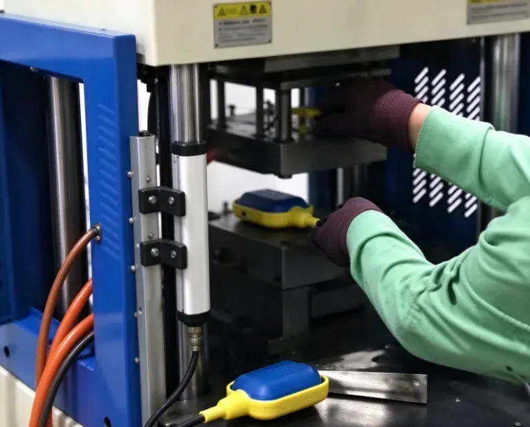
This DEBOGE project uses a vertical injection molding machine to overmold the yellow outer edge and cable outlet of a float switch. A prepared component and its cable are positioned in the tool before plastic is injected to form these protective features.
The production task brings together two areas that need consistent positioning: the perimeter of the housing and the point where the cable leaves it. The molding arrangement must support the component, locate the cable and reproduce the required edge geometry through repeated cycles.
The product and the molding scope
Cable-equipped float switches are used for liquid-level control in pumps, water tanks, drainage systems, sewage treatment equipment and industrial fluid systems. Their housing, cable entry and internal assembly must work together under the conditions specified for the finished product.
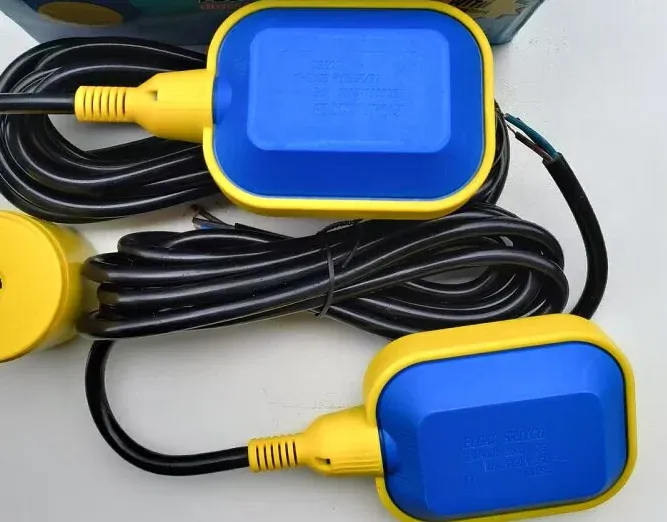
The supplied product has a blue main body, a yellow outer edge and a black cable passing through a ribbed yellow outlet. This project covers the yellow overmolding stage. The prepared component is placed in the mold so that the yellow material can form the specified perimeter and cable-exit section.
| Item | Project configuration |
|---|---|
| Product | Cable-equipped float switch |
| Molding scope | Yellow outer edge and cable outlet |
| Process | Injection overmolding around a prepared component and cable |
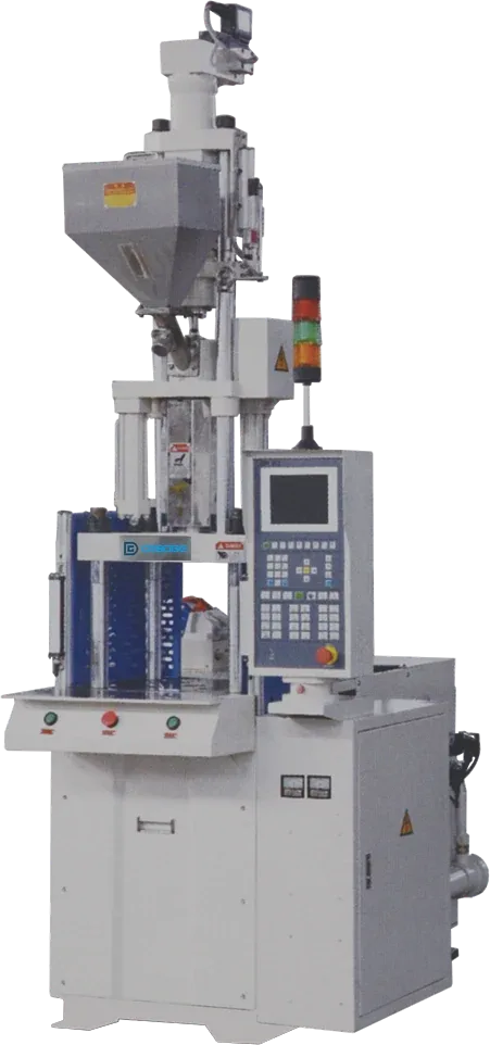
| Equipment | Vertical injection molding machine |
| Component handling | Operator handling at the open mold |
| Main control points | Component location, cable alignment, edge geometry and molded appearance |
The operation combines insert molding, where an existing component is placed in the tool, with overmolding, where material is formed around part of that component. Defining the molding boundary is an essential first step when reviewing the tool and machine.
Why the vertical layout matters
The project documentation identifies access for component placement as a reason for selecting vertical injection molding. The operator can approach the open lower mold, position the prepared assembly and arrange the cable before the molding cycle begins.
This access is useful for a part with a cable extending beyond the molded section. The loading method needs to keep the cable clear of the closing surfaces and place the housing against the intended locating references. Once positioned, the tool must retain the assembly during closing and injection.
Repeatability depends on the relationship between the part, the mold and the handling method. When assessing a custom vertical molding solution, the tooling review should cover support for the prepared housing, the cable path and access for removal as well as the machine configuration.
The overmolding sequence
The process described for this project follows a repeated preparation, molding and inspection sequence:
- Prepare the assembly. Check the component and cable before loading, including the surfaces and sections that will enter the mold.
- Locate the part and cable. Position the prepared component in the open tool and align the cable outlet with the intended molding area.
- Close the mold and inject. With the assembly located by the tooling, inject the plastic that forms the yellow outer edge and cable-exit protection.
- Cool and remove. Allow the molded section to cool, then remove the part while protecting the cable and formed features.
- Inspect the molded areas. Check the outer edge, cable position, surface finish and any features specified for subsequent assembly or testing.
What to control at the housing edge and cable outlet
At the outer edge, the product drawing should define the required profile and the surfaces that need to remain consistent. Inspection should look for incomplete filling, flash, deformation and alignment with the prepared housing.
At the cable outlet, check the cable’s position and the molded protective geometry. The cable must remain correctly located through molding and removal. Any required cable-retention or bending checks should be defined for the finished assembly.
The material review also needs the intended overmolding grade, the prepared housing material and the cable-jacket specification. These inputs help assess the material combination and molding conditions for the actual component.
Because float switches may operate in wet environments, sealing performance requires its own acceptance checks. The molded edge and cable entry are relevant inspection areas, but any leak, immersion or functional test must follow the finished product’s specified requirements. A clean appearance alone does not establish a waterproof rating.
Reported outcome and inputs for a similar project
The project report describes easier placement of cable-related components and a more controlled, repeatable molding process. It also reports consistent appearance around the housing edge and cable outlet. These are qualitative observations from the project.
For a similar overmolding application, start with the assembly drawing and a representative sample. Identify the area to be overmolded, the surfaces to remain exposed, the cable specification and the required inspection criteria. Target output and handling requirements can then be considered alongside the tool and material selection.
Common questions
Which part of the float switch is overmolded in this project?
The yellow outer edge and the yellow cable-outlet section are formed around a prepared float-switch component and cable.
Does the blue-and-yellow appearance establish a two-shot process?
The confirmed operation is overmolding the yellow sections. The product’s appearance does not establish a two-shot machine configuration.
How is sealing performance checked?
The acceptance plan should specify the required checks for the housing interface and cable entry, together with any leak, immersion or functional testing appropriate to the finished switch.
What information is needed to select the machine and mold?
Provide the assembly drawing or sample, overmolding boundary, housing and cable materials, intended molding material, tolerances, production target and handling requirements.
Discuss your float switch overmolding project
DEBOGE can review the prepared assembly, cable outlet, overmolding geometry and production requirements together. Clear part information helps define the tooling, machine configuration and loading arrangement for the application.
Discuss your float switch overmolding requirements with DEBOGE.
Related Reading
Have a similar application?
Contact Deboge engineering to discuss your production requirements and machine configuration.