
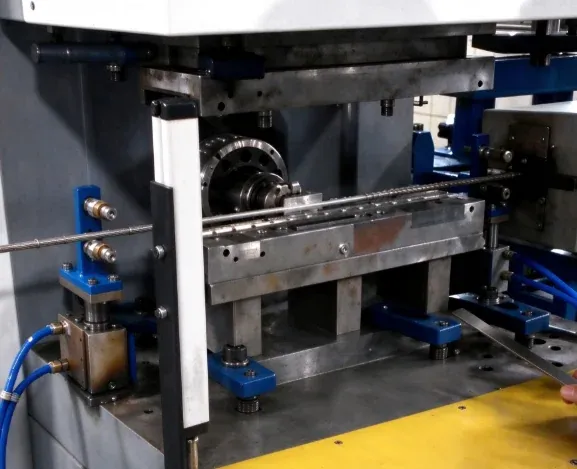
Diamond Wire Saw Coating with Vertical Injection Molding
See how a vertical injection molding machine coats diamond wire saw assemblies, with insert positioning, dimensional consistency and an around-20-second cycle.
2026-10-19 | 5 min read | Industry: Stone cutting and construction demolition
In this project, DEBOGE uses a vertical injection molding machine for diamond wire saw coating. The process places the wire-saw assembly and required inserts in a mold, then injects plastic around the specified section. The reported molding cycle is around 20 seconds, with dimensional consistency as the customer’s main production requirement.
For this application, machine selection has to account for how the wire and inserts are positioned before each shot. The mold must locate the assembly, the operator must be able to load it consistently, and the molding conditions must produce the required geometry from cycle to cycle.
The product and project configuration
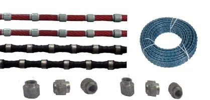
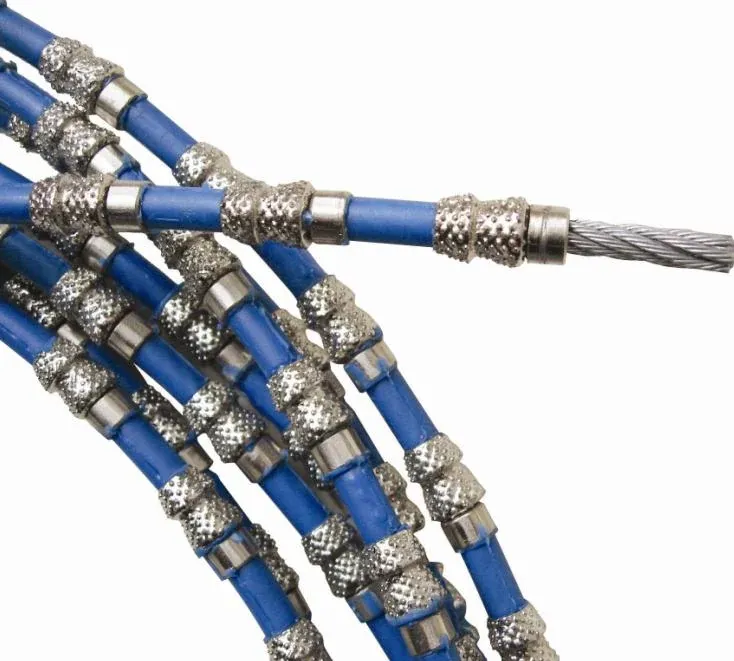
Diamond wire saws are used in stone quarry cutting, building demolition and renovation. Their construction combines diamond beads with a steel-wire assembly. This case concerns the plastic coating operation, carried out by molding material around or along the insert structure.
The process is both insert molding, because the assembly is placed in the tool before injection, and overmolding, because the plastic is formed around an existing structure. The tooling defines the portion to be coated and the geometry of that molded section.
| Item | Configuration in this project |
|---|---|
| Product application | Diamond wire saw coating |
| End applications | Building demolition, renovation and stone quarry cutting |
| Machine | Vertical injection molding machine |
| Molding process | Plastic insert molding around the wire-saw assembly |
| Insert placement | Operator placement into the mold |
| Reported cycle time | Around 20 seconds per molding cycle |
| Main production requirement | Dimensional consistency |
The approximate cycle describes the molding operation in this project. Output in metres per hour also depends on the length coated per shot and the handling sequence; those values are not specified in this case.
Why the vertical layout was selected
The customer needed a working arrangement that supported the placement of steel wire and metal inserts. Access to the open lower mold allows the operator to locate these components before the mold closes. That access matters when the assembly includes flexible wire that must follow a defined position through the tooling.
The project report identifies gravity-assisted placement as one benefit of the vertical arrangement. Gravity can assist the loading step, while the mold’s locating and retaining features must keep the assembly in its required position through closing and injection. Tool access and insert retention therefore need to be considered together.
The machine layout is one part of the solution. The mold, insert preparation and repeated loading method determine whether that access translates into a consistent production routine. These are also relevant inputs when reviewing custom vertical molding solutions for a different wire-saw geometry.
The coating cycle
The documented process begins with the operator placing the required inserts in the mold area. The mold closes, and plastic is injected around or along the insert assembly to form the specified coated section. The next loading and molding cycle then repeats the sequence.
The reported cycle of around 20 seconds gives a reference for this particular setup. A different coated length, insert arrangement, material or handling method requires its own cycle assessment.
What to review for a similar wire saw coating project
The wire assembly and its position in the tool
Provide the assembly drawing and samples that show the steel wire, beads and any additional inserts required for the part. The tooling review should identify the locating references, the surfaces to be coated and those that must remain exposed.
Wire support outside the molded section also deserves attention. For a proposed setup, review how the incoming assembly is presented to the mold and how its remaining length is supported during loading and removal. This helps define a practical handling arrangement without relying on the operator to hold the assembly in position during molding.
The dimensions that define an acceptable coated section
State the required coating geometry, molded length, insert positions and tolerances on the product drawing. Where spacing is a controlled feature, define its reference points so the tool and inspection method use the same requirement.
This turns a general request for consistency into dimensions that can be checked. Sample evaluation can then compare the molded section with the drawing and confirm that the insert arrangement remains correct after molding.
The coating material and acceptance criteria
The intended molding material and grade should be provided with the assembly details. Material selection, surface condition and mold design need to be reviewed together for the specific wire-saw construction. The material cannot be identified reliably from the finished product’s colour or appearance.
For a new project, define any required coating-retention and functional checks alongside dimensional inspection. Those checks belong to the customer’s product validation requirements; the approximately 20-second molding cycle alone does not establish cutting performance or service life.
Reported project outcome
The project report identifies dimensional consistency as the key result achieved with the vertical molding arrangement. Accessible insert placement and repeatable clamping and injection conditions supported the repeated production of the molded section.
For another industrial insert molding application, the useful starting point is the relationship between the assembly, the mold and the loading sequence. The wire-saw coating machine should be configured around those requirements, with the desired output evaluated for the actual part and process.
Common questions
What process does this diamond wire saw coating machine use?
This project uses plastic injection overmolding. The wire-saw assembly and required inserts are positioned in a mold before plastic is injected around the specified section.
Is the reported 20-second cycle a production guarantee?
No. Around 20 seconds is the reported molding cycle for this project. The coated length per shot, handling time and other production requirements need to be established before calculating output for another setup.
What is needed to assess a different diamond wire saw?
Send the assembly drawing or sample, wire and insert specifications, intended coating material, required molded geometry and tolerances. Include the target output and the proposed way to supply and collect the wire assembly at the machine.
Discuss your diamond wire saw coating requirements
DEBOGE can review your wire-saw assembly, tooling requirements and production target together. Product drawings, insert samples and material details provide the basis for discussing a suitable machine and loading arrangement.
Related Reading
Have a similar application?
Contact Deboge engineering to discuss your production requirements and machine configuration.