
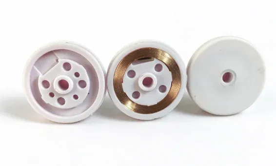
Animal RFID Ear Tag Insert Molding with a Vertical Rotary Machine
Explore animal RFID ear tag insert molding with manual insert loading, a vertical rotary machine, an eight-cavity mold and a reported cycle around 20 seconds.
2026-10-19 | 5 min read | Industry: Livestock identification and traceability
Producing an animal RFID ear tag involves more than forming its plastic exterior. The embedded RFID component must be positioned in the mold before injection, and the molding process must accommodate that component. When inserts are placed manually, the time and movement needed for loading also influence the production cycle.
This DEBOGE project uses a vertical rotary injection molding machine, manual insert placement and an eight-cavity mold. The reported cycle is around 20 seconds. With one upper mold and two lower molds, the machine allows insert preparation at the loading station to overlap with molding at the other station.
The ear tag and its production requirements
Animal RFID ear tags support livestock identification and traceability. For the molding supplier, the immediate task is to produce the specified tag component while locating and encapsulating the RFID insert correctly. The insert, plastic geometry and mold positioning features therefore need to be reviewed together.
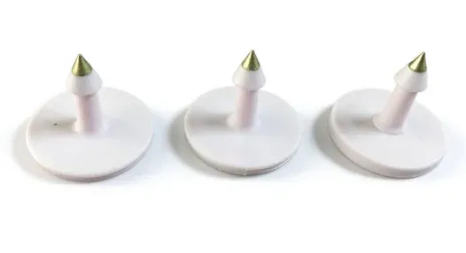
The supplied photographs also include pin components used in an ear-tag assembly. These views help distinguish the different parts of the product; they do not establish that every pictured component is produced in the same mold.
| Item | Configuration in this project |
|---|---|
| Product application | Animal RFID ear tags |
| Industry | Livestock identification and traceability |
| Process | Insert molding |
| Insert loading | Manual placement |
| Machine | Vertical rotary injection molding machine |
| Mold arrangement | One upper mold and two lower molds |
| Cavities per cycle | 8 |
| Reported cycle time | Around 20 seconds |
| Production objective | Improve workflow efficiency and product consistency |
The cavity count and cycle time describe this project. They do not establish the output of complete, inspected ear-tag assemblies or a guaranteed cycle for another tag design.
How the rotary arrangement supports manual loading
The production challenge was to combine accurate insert placement with a repeatable loading routine. The operator needed access to the lower mold and a working position that reduced movement between repeated tasks.
The selected rotary-table injection molding machine uses two lower molds with one upper mold. While one lower mold is at the molding station, the other is available for preparation according to the machine’s permitted operating sequence. After the molding operation and loading tasks are complete, the table indexes to exchange their positions.
This arrangement overlaps tasks that would otherwise have to wait for access to the same molding position. Its benefit depends on the complete sequence: placing all inserts, removing molded parts, and returning the station to a condition ready for indexing.
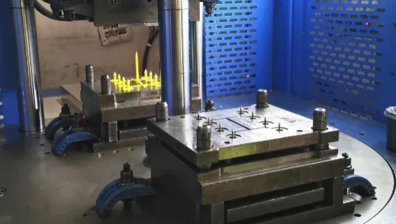
The vertical arrangement also provides access to the open lower mold for insert placement. Gravity and the tool’s locating features assist placement before closing; the tooling must still retain the insert in its required position during molding.
The following video accompanies the project and shows the production application.
What to review for a similar RFID ear tag project
Insert location and the molded geometry
Start with the finished-part drawing and the RFID insert dimensions. Identify the surfaces that must be covered by the molding resin and those that must remain exposed. The mold review should establish how the insert is located, supported and retained, including how the operator confirms correct placement before the station advances.
For an eight-cavity tool, the loading method must work across all eight positions. Reviewing the operator’s access and loading sequence is therefore part of the tooling discussion, alongside the part dimensions.
Molding conditions and functional checks
For a new application, provide the intended resin grade and the RFID component supplier’s processing limits. Those inputs are needed to assess the molding conditions around the insert. The resin and electronics should be evaluated together for the specific part rather than selected from the tag’s appearance alone.
Define the required checks for the molded component and the completed assembly, including dimensions, visible molding defects and RFID function. These are review and acceptance requirements for a proposed project; this case report does not provide measured read performance or field durability results.
The balance between loading and molding
The two lower molds create an opportunity to prepare inserts during molding. The attainable cycle still depends on whether the operator can complete the required handling within the available time, as well as the molding and indexing sequence.
For planning purposes, review a complete cycle with the actual inserts and tooling. The reported around-20-second cycle is a reference for this installation, not a substitute for assessing a different product, material or loading method.
Reported project outcome
The project report describes easier manual insert placement, less operator movement, reduced waiting and improved product consistency after adopting the rotary arrangement. These are qualitative reported results; no measured percentage improvement or production yield is provided.
The useful design principle is the relationship between insert handling and machine layout. Here, the eight-cavity tool provides multiple molding positions per cycle, while the two lower molds allow preparation and molding to overlap. Both features contribute to the working sequence of the insert molding application.
Common questions
Is insert loading automatic in this project?
No. Inserts are placed manually. The rotary arrangement allows preparation at one station while molding takes place at the other, according to the machine’s operating sequence.
What are the mold arrangement and cycle time?
The documented configuration has one upper mold, two lower molds and eight cavities per cycle. The reported cycle is around 20 seconds for this application.
What information is needed to assess another animal RFID ear tag?
Provide the finished-part drawing or sample, RFID insert specifications, intended resin grade, target output and product acceptance criteria. Clarify which component is to be molded and which assembly or inspection operations are required afterward.
Discuss your animal RFID ear tag molding project
Send DEBOGE your ear-tag drawings or samples together with the RFID insert details and production requirements. These inputs help review the machine arrangement, mold configuration and manual loading sequence as one production process.
Discuss your animal RFID ear tag molding requirements with DEBOGE.
Related Reading
Have a similar application?
Contact Deboge engineering to discuss your production requirements and machine configuration.