
Seat Belt D-ring Insert Molding: Four-Cavity Production with Robot Handling
Explore four-cavity seat belt D-ring insert molding with a rotary vertical machine, robot handling and an approximately 25-second reported project cycle.
2026-09-29 | 5 min read | Industry: Automotive seat belt components
A seat belt D-ring, also called a guide ring, combines a shaped metal insert with molded plastic. Producing this component requires the insert to stay in the correct position while plastic forms around the specified areas. The production sequence must also allow finished parts to be removed and the next inserts to be loaded between shots.
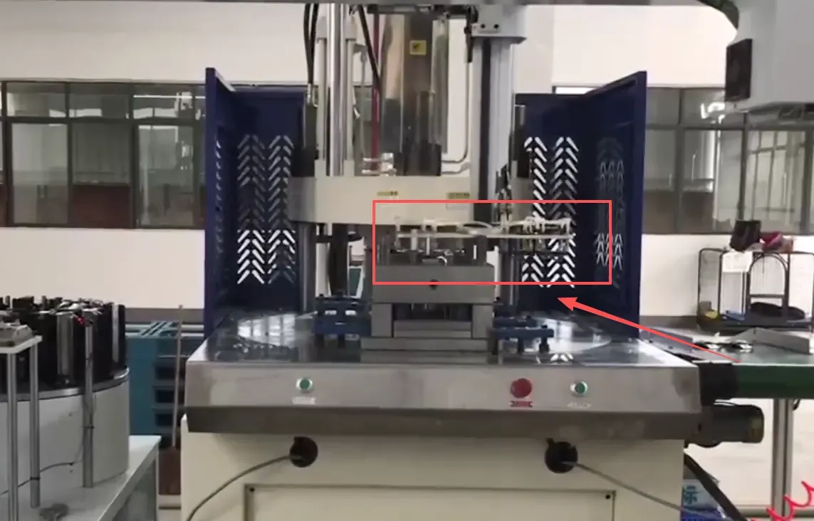
This DEBOGE project uses a rotary vertical injection molding machine with one upper mold and two lower molds. A four-cavity mold produces four components per molding cycle, with a reported cycle time of approximately 25 seconds. Robot-assisted part removal and insert loading take place at the handling station while molding proceeds at the other position.
The D-ring component and project configuration
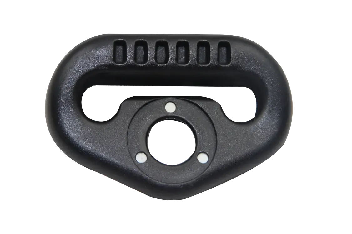
The product photographs show the metal insert alongside the plastic-overmolded D-ring. The circular opening and elongated slot remain part of the finished geometry, while plastic covers selected areas of the metal component. The tooling must reproduce this relationship between exposed features and molded coverage.
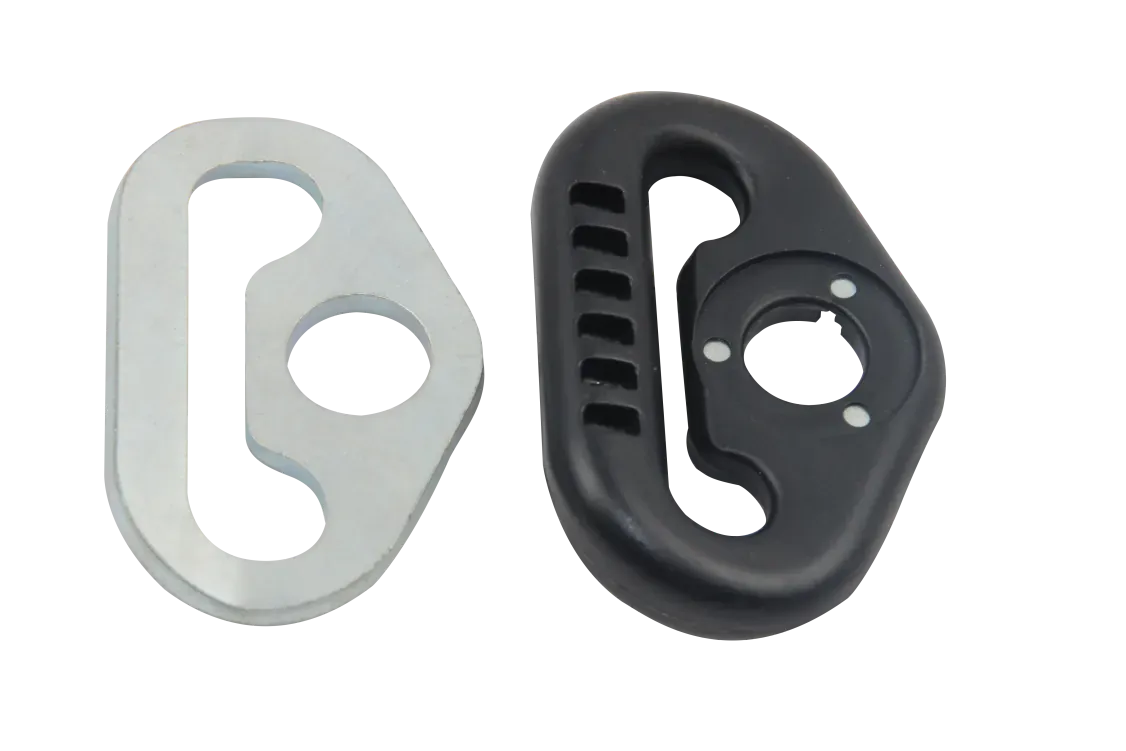
In this insert molding application, the metal component is made before molding and placed into the lower tool. Plastic is then injected around it to create the combined metal-and-plastic part.
| Item | Configuration in this project |
|---|---|
| Product | Automotive seat belt D-ring / guide ring |
| Process | Metal insert molding with plastic overmolding |
| Machine type | Rotary vertical injection molding machine |
| Mold arrangement | One upper mold and two lower molds |
| Cavity count | 4 cavities |
| Parts per molding cycle | 4 |
| Reported cycle time | Approximately 25 seconds for this project |
| Handling | Robot-assisted finished-part removal and insert loading |
| Operating sequence | Molding at one station while loading and unloading at the other |
The approximately 25-second cycle describes this part and production configuration. A different insert, plastic geometry or handling sequence requires its own cycle assessment.
How the rotary table and robot share the cycle
The production advantage of the rotary table arrangement is the overlap between molding and handling. One lower mold is at the molding position. The other is accessible for removing the previous parts and placing the next metal inserts. The two lower molds alternate beneath the same upper mold.
The repeating sequence is:
- Mold the current set of inserts. Plastic forms around the metal components in the four-cavity tool at the injection position.
- Prepare the other lower mold. During that molding cycle, the robot removes finished parts and places new inserts at the handling station.
- Transfer the prepared tool. Once molding and handling are complete and the machine is ready, the rotary table moves the prepared lower mold to the molding position.
- Repeat at the alternate station. The lower mold containing the newly molded parts moves to the handling position for unloading and reloading.
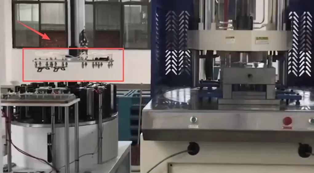
This arrangement reduces the waiting associated with carrying out molding and all handling tasks entirely in sequence. Its effectiveness depends on the robot completing the required removal and loading work within the available part of the cycle. Four cavities increase the number of parts molded in a shot, while the handling sequence determines how the tool is prepared for the next shot.
For a comparable project, the cycle review should therefore include both the molding operation and the time needed to grip, transfer, locate and release the parts and inserts. Assessing only injection time would leave out work that can affect the overall production rhythm.
Tooling and handling considerations for D-ring overmolding
Insert location and plastic coverage
The D-ring insert must be located relative to the plastic cavity before the mold closes. Its position affects the relationship between the circular opening, elongated slot and surrounding molded profile. The lower mold provides access for placing the insert, but the locating features and insert dimensions determine how it is supported.
For a new D-ring design, the tooling review should establish which metal surfaces remain exposed, which areas receive plastic and how the insert is held during transfer and molding. Insert variation and the required finished dimensions need to be considered together.
Robot access and four-cavity preparation
Robot handling must be coordinated with the cavity layout. For a similar installation, the engineering review should cover access to each insert position, how finished parts are gripped and where inserts can be supported without interfering with their placement in the mold.
The source of the next inserts and the destination of the finished parts also belong in that review. These handling requirements should be defined alongside the tool and machine configuration, rather than added after the molding sequence has been fixed.
Material and part requirements
The production brief for a new part should identify the plastic grade, metal insert specification, required dimensions and functional acceptance criteria. The photographed geometry alone is not enough to select a resin or establish the process settings.
This is the same relationship between insert preparation, tooling and handling that appears in other automotive insert molding applications. Each component still needs an assessment based on its own drawing, materials and production requirement.
The machine also supports seat belt tongue overmolding
The machine used for this project can also produce plastic-overmolded seat belt tongues, sometimes called latch plates, with tooling and handling configured for that product. Both tongues and D-rings combine metal inserts with molded plastic, but their part geometry and mold requirements differ.
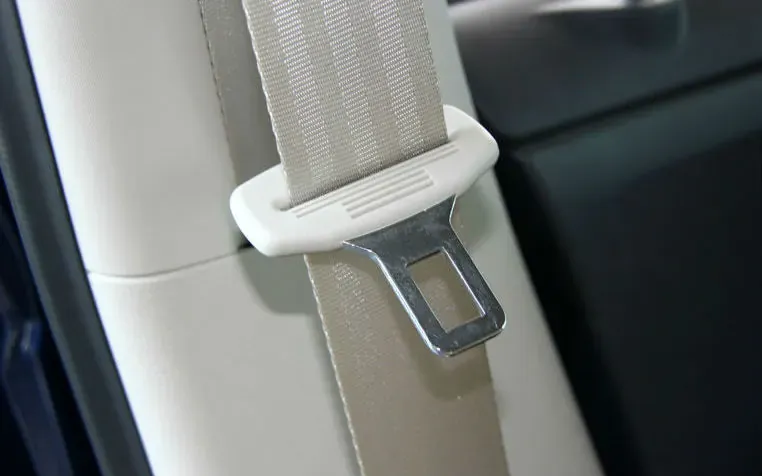
For a tongue application, the mold cavity, insert location and robot gripping arrangement need to match the tongue design. The four-cavity layout and approximately 25-second cycle reported above apply to the D-ring project; tongue production should be assessed against its own part and output requirements.
Project outcome and requirements for a similar component
The project combines four parts per shot, an approximately 25-second reported cycle and robot-assisted handling in a rotary-table production sequence. The practical benefit is that the next set of inserts can be prepared while molding continues at the other station.
To assess a similar D-ring project, send DEBOGE the finished-part drawing or sample, metal insert drawing, intended plastic material, cavity requirement and production target. Information about how inserts arrive at the machine and how molded parts should be collected will help define the handling arrangement.
These inputs allow the machine, mold and robot sequence to be reviewed as one production process.
Common questions
What component is produced in this case?
The product is an automotive seat belt D-ring, also known as a guide ring. It combines a metal insert with plastic overmolding.
Why does the configuration use two lower molds?
The two lower molds alternate between molding and handling positions beneath one upper mold. This lets removal and insert loading at one station overlap with molding at the other.
What does the robot do?
The robot assists with removing finished components and placing new metal inserts into the mold. The placement sequence is coordinated with the rotary table and four-cavity tool.
Is the approximately 25-second cycle guaranteed for other D-rings?
No. It is the reported cycle for this project. Another D-ring requires a cycle assessment that accounts for its insert geometry, plastic features, tooling and handling operations.
Discuss your seat belt D-ring molding project
Share your D-ring or seat belt tongue drawing or sample and the intended production requirement. DEBOGE can review the machine arrangement, insert tooling and robot handling sequence needed for the application.
Discuss your seat belt D-ring insert molding requirements with DEBOGE.
Related Reading
Have a similar application?
Contact Deboge engineering to discuss your production requirements and machine configuration.