
Seat Back Sinuous Spring Assembly: PP Overmolding on DA-2100.2R
See how DA-2100.2R rotary table molding combines manual spring wire loading with PP overmolding for automotive seat back supports in a one-cavity project.
2026-09-29 | 5 min read | Industry: Automotive seating components
An automotive seat back support can combine a shaped spring steel wire insert with molded plastic features. Making that assembly requires the wire to stay in its intended position while plastic forms around selected areas. It also requires a practical way to load the next insert between molding cycles.
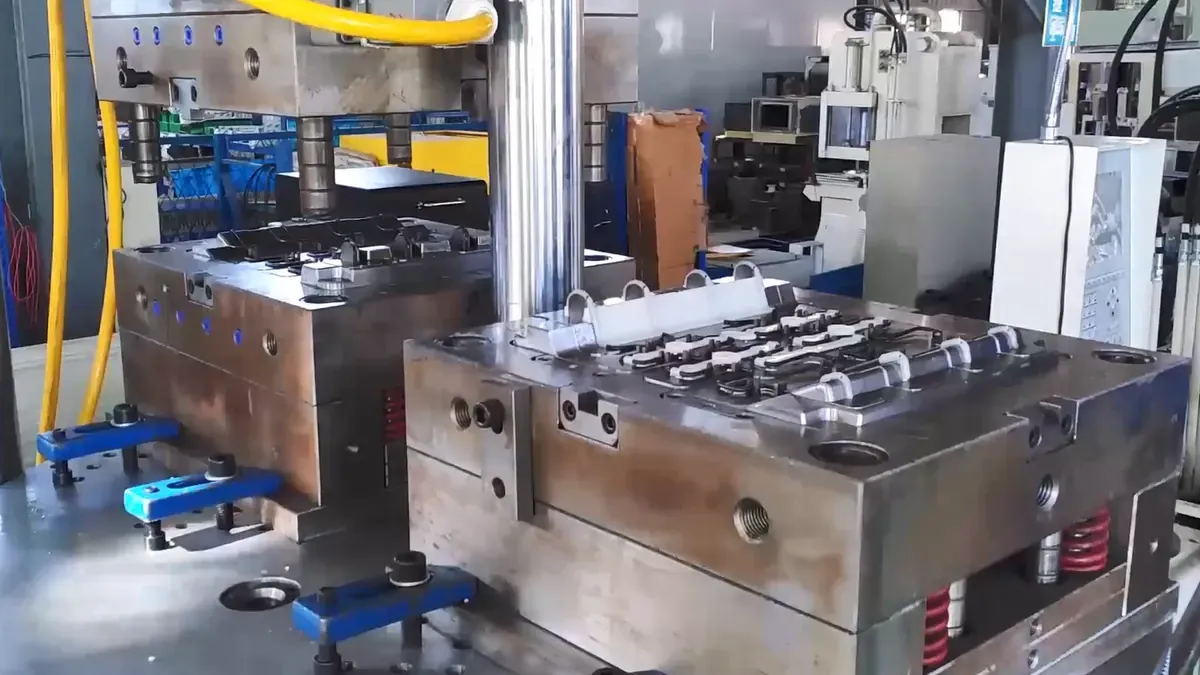
For this Seat Back Sinuous Spring Assembly project, DEBOGE supplied a DA-2100.2R vertical rotary table injection molding machine for PP overmolding. The configuration uses a one-cavity mold and manual insert loading, with a reported cycle of approximately 45 seconds per shot. The rotary table allows preparation at the loading station to overlap with molding at the injection position.
The product and project configuration
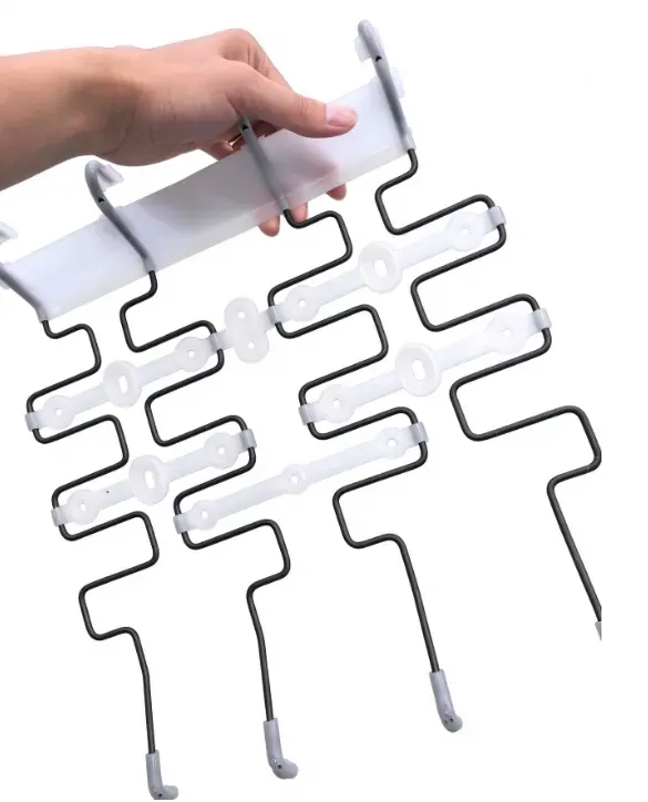
The component is used in an automotive seat back. Its formed spring steel wire remains visible between the molded PP sections, while the plastic features provide the specified connection and positioning geometry. The objective is to reproduce that metal-and-plastic arrangement consistently, ready for the intended seat assembly.
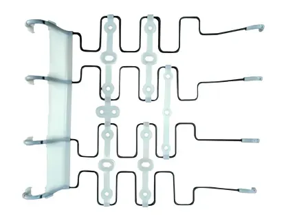
This is an insert molding application: the metal insert is prepared before molding, positioned in the tool and incorporated into the finished part during injection. The machine is selected around both the molding requirements and the handling of that insert.
| Item | Configuration in this project |
|---|---|
| Product | Seat Back Sinuous Spring Assembly |
| Industry | Automotive seating components |
| Machine | DA-2100.2R |
| Machine arrangement | Vertical clamping, vertical injection and rotary table |
| Insert | Spring steel wire |
| Molded material | PP |
| Mold cavity count | 1 cavity |
| Insert loading | Manual placement; no automatic insert feeding system |
| Reported cycle | Approximately 45 seconds per shot for this project |
The approximately 45-second cycle per shot is a reference for this part and mold. A different wire layout, plastic section or loading requirement needs its own cycle assessment.
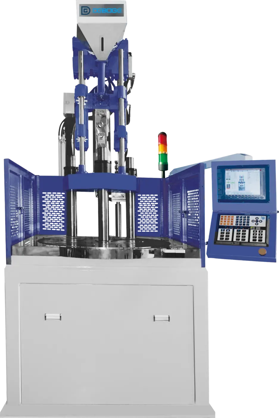
The DA series uses vertical clamping and vertical injection. In this project, the lower mold provides an accessible location for placing the shaped wire before it moves to the injection position. The standard vertical machine overview explains this machine structure; the rotary table adds the transfer between loading and molding positions.
How the rotary table coordinates loading and molding
The main production requirement was to use operator time effectively while retaining manual spring-wire loading. A rotary table machine separates the accessible loading position from the injection position, allowing the next insert to be prepared while the current part is molded.
The sequence in this project is:
- Place the spring wire. The operator locates the shaped insert in the lower mold at the loading station.
- Mold at the other position. PP is injected around the insert already at the injection position while preparation continues at the loading side.
- Index the table. After the molding cycle is complete and the machine is ready for transfer, the prepared insert moves to the injection position.
- Unload and prepare again. The molded assembly moves to the unloading side, where it is removed before the next insert is placed.
The useful change is the overlap between these tasks. Manual placement does not automatically mean that the machine must wait through the entire loading operation after every shot. The benefit depends on the loading and unloading work fitting the molding sequence, together with the machine’s transfer and operating conditions.
This project does not use an automatic insert feeding system. Its reported efficiency improvement comes from the arrangement of the work around the rotary table, without changing spring-wire placement into an automated operation.
What needs to be controlled around the wire insert
Wire position and mold location
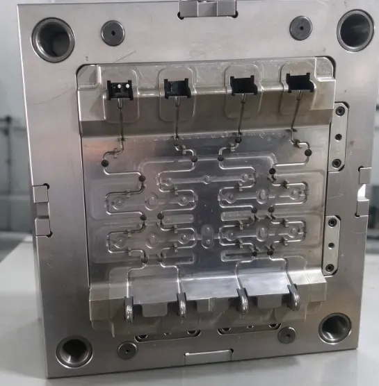
The spring wire has a formed shape, so the mold must locate more than a simple straight pin. Its position determines where the PP features form relative to the exposed wire sections and the points used in the seat assembly. A displaced insert can change that relationship even if the plastic cavity fills.
For a comparable project, the tooling review should cover how the wire sits in the lower mold, how its shape is supported and how the required position is maintained through table transfer and mold closing. These are product-specific tooling questions; the vertical layout alone does not establish dimensional accuracy.
PP coverage and the finished assembly
The molded material for this project is PP. The required coverage is selective: some wire sections remain exposed, while others are surrounded by molded plastic features. The product drawing therefore needs to define both the plastic geometry and its position relative to the metal insert.
For a new seat back support, the PP grade, insert drawing, dimensional criteria and required functional checks should be agreed before finalizing the process. The presence of plastic around steel does not by itself establish bond strength or fatigue performance. Those requirements need appropriate product evaluation.
This approach also applies to other automotive insert-molded components, where the location of the insert and the geometry of the surrounding plastic must be considered as one assembly.
Project outcome and requirements for a similar part
The reported result was a more efficient production workflow while retaining manual insert loading. The rotary table allows loading and injection to proceed in parallel, reducing the waiting associated with carrying out the two operations entirely in sequence.
To assess a similar seat back component, send DEBOGE the part drawing or sample together with the insert drawing, PP grade, cavity requirement and output target. The review should also cover permitted variation in the wire shape, loading and unloading access, and the dimensions or functional checks used to accept the finished assembly.
These inputs help connect the machine configuration, mold design and manual handling sequence to the actual production requirement.
Common questions
Which machine is used for this seat back spring project?
The machine is the DA-2100.2R, configured with vertical clamping, vertical injection and a rotary table for this insert molding application.
Is the spring wire loaded automatically?
No. The operator places the spring steel wire insert manually. The project does not include an automatic insert feeding system; the rotary table coordinates loading with molding at the other position.
What material and cavity count are used?
PP is molded around the spring steel wire in a one-cavity mold. The specific PP grade and part acceptance requirements should be established separately for any new project.
Can the 45-second cycle be used to plan another product?
It can be used as a reference for this case, but a new product requires its own assessment. Wire geometry, plastic features, tooling and the time needed to load and unload the part all affect the production sequence.
Discuss your seat back insert molding project
Send DEBOGE the seat back support drawing or sample and describe the spring-wire insert, plastic material and intended production requirement. Our engineering team can review how the mold, machine and handling sequence should work together.
Discuss your seat back spring molding requirements with DEBOGE.
Related Reading
Have a similar application?
Contact Deboge engineering to discuss your production requirements and machine configuration.