
Insulation Piercing Connector Insert Molding: A Four-Machine Project in Brazil
See how four DA-1200R machines combine metal insert molding, overmolding, robotic handling and automatic assembly for a Brazilian electrical connector project.
2026-09-17 | 7 min read | Industry: Electrical power distribution
For a Brazilian customer manufacturing insulation piercing connectors (IPCs), the production task extended from placing metal inserts in the mold to assembling the finished connector. Two component types required a first molding operation followed by overmolding, with feeding and transfer equipment connecting the stages.
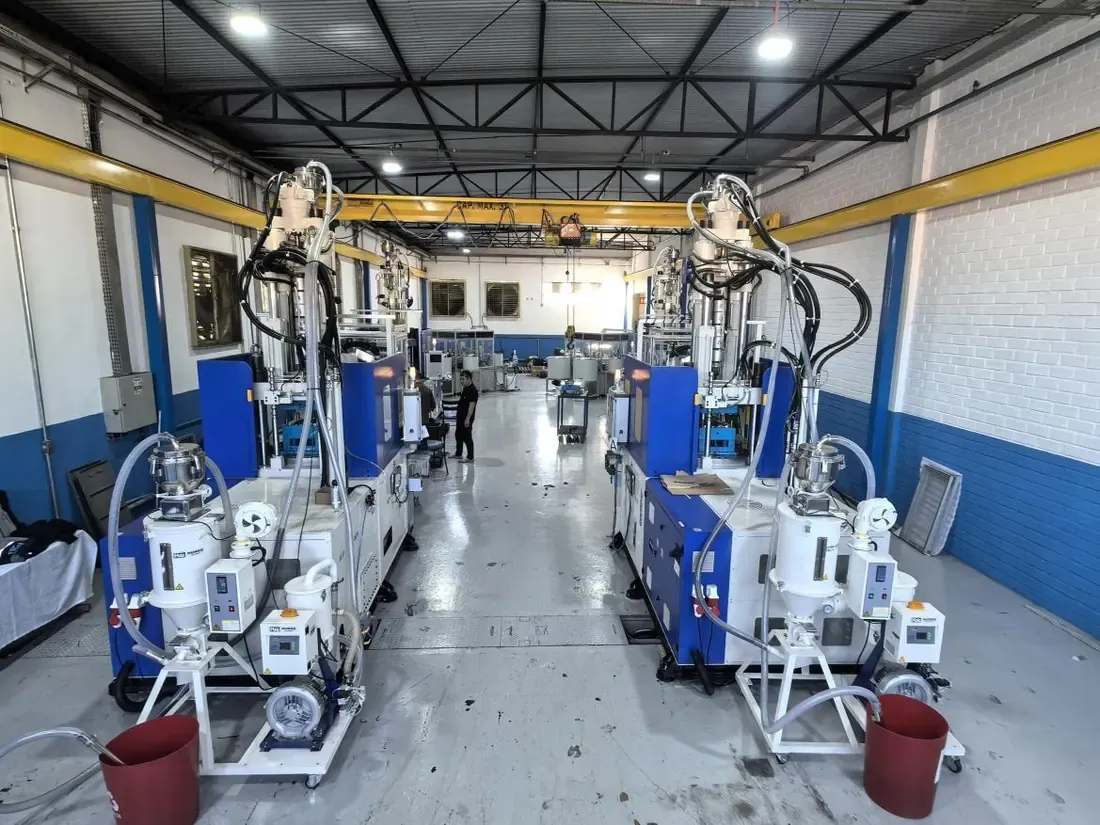
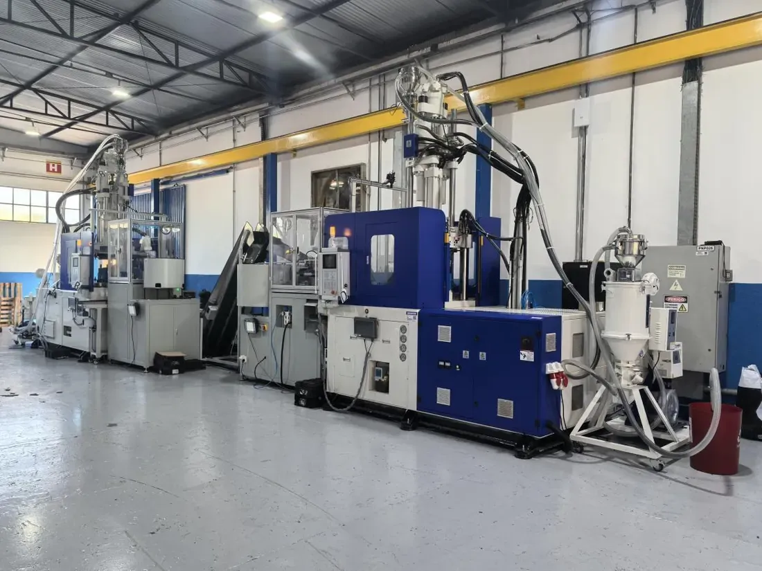
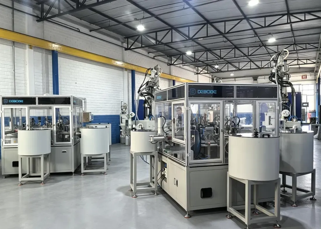
DEBOGE supplied four DA-1200R rotary-table vertical injection molding machines, integrated with vibratory bowl feeding, robotic handling, conveyors and two downstream automatic assembly units. The project uses two molding paths: A → C for the oval-type component and B → D for the hexagonal-type component.
Start with the connector components
The product requires metal sheet inserts to be placed in the mold before injection. Their position is therefore part of the molding process, alongside forming the surrounding plastic. Both component types then undergo a separate overmolding stage before downstream assembly.
The line handles two component types, referred to in this project as oval-type and hexagonal-type. Each follows its own first-molding and overmolding path.
Four molding machines, two component paths
Machines A and B perform the first molding operations. Machines C and D perform the corresponding overmolding operations. Conveyors transfer the first-molded components toward the next molding stage.
| Component path | First molding | Transfer | Overmolding |
|---|---|---|---|
| Oval-type: A → C | Machine A | Conveyor transfer to the overmolding stage | Machine C |
| Hexagonal-type: B → D | Machine B | Conveyor transfer to the overmolding stage | Machine D |
This arrangement pairs each first-molding stage with its corresponding overmolding machine, so feeding and transfer can be planned around the two component paths.
Each molding machine has two vibratory bowl feeders, giving eight feeders for the four molding machines. The two automatic assembly units operate downstream of molding and overmolding.
Why this project uses rotary-table insert molding
For this connector, loading metal sheets is a repeated production operation. The mold must locate the inserts in the required position before closure and injection. The loading arrangement also needs to give the handling system a repeatable way to present each insert.
The vertical mold-opening arrangement provides access for placing the inserts. The rotary table separates the loading position from the molding position, allowing insert loading on one side while molding proceeds on the other. This overlap is the practical reason for considering a rotary-table molding machine when insert loading forms a significant part of the production sequence.
The table alone does not determine the line’s output. Insert presentation, robot movement, mold access and the molding cycle must fit together. For a similar project, the engineering review should establish how each insert is located and retained, where the handling system can approach, and when the table can move. The metal insert molding application overview provides related machine-selection context.
Feeding, robotic pickup and conveyor transfer
The vibratory bowls arrange and feed components for robotic pickup. Presenting components in a repeatable orientation gives the handling system a defined starting position and reduces the need for repetitive manual sorting at that step.
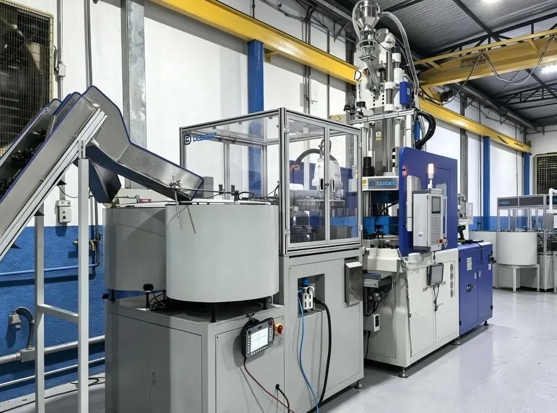
Conveyors connect first molding with overmolding so that transfer is included in the production layout. For a new line, the handoff needs the same attention as the mold itself: how the part arrives, which surfaces can be gripped, and how its orientation is preserved for the next operation.
These are useful questions when specifying automation-ready vertical molding equipment. Machine selection, feeding and part handling should be reviewed together, because a molding cycle can only contribute to finished output when the following stages can receive the parts.
Downstream assembly completes the connector
After molding and overmolding, the components move to two automatic assembly units. The assembly sequence places the hexagonal component first. This order is part of the project requirements and should be carried through into the assembly tooling and handling plan.
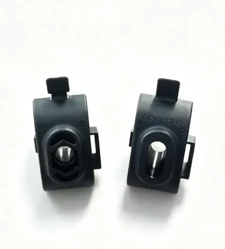
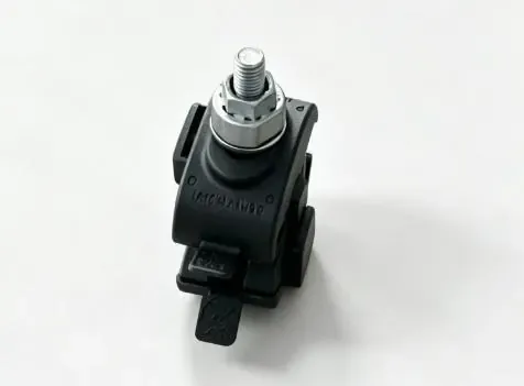
The finished sample below shows the product after assembly. It also explains why the production scope includes more than injection molding: the separate molded components must reach an assembly process in the required condition and sequence.
The integrated layout is intended to reduce repetitive transfer work and maintain a consistent assembly order. Evaluating a similar project therefore means reviewing the complete path from loose inserts to accepted assembled connectors, including the handoffs between equipment.
Planning a comparable connector line
Start with the product and its process sequence, then define the equipment. The following information helps turn an initial inquiry into an engineering discussion:
- Product and insert drawings: identify each component, the metal inserts and the positions that must be maintained during molding.
- Materials and molding stages: specify the intended material at each stage and provide samples showing the required first-molded and overmolded condition.
- Production requirement: state the required accepted connectors per shift and planned operating hours, so the molding and assembly stages can be assessed together.
- Transfer and assembly requirements: describe the required component orientation, assembly order, inspection points and finished-part collection method.
- Site arrangement: provide the available floor space and access requirements for feeding, operation and maintenance.
DEBOGE can use this information to discuss machine selection, mold process planning, production layout and automation integration for the application.
Questions about this IPC production approach
Does every insulation piercing connector need four molding machines?
No. Four DA-1200R machines are the configuration of this project. Another connector may require a different arrangement based on its component design, molding stages and production requirement.
Is an overmolded component the same as an assembled connector?
No. In this project, overmolding is a molding operation performed on the first-molded component. Final assembly follows as a separate downstream process. See the overmolding process overview for the general distinction.
What information is needed to specify a comparable line?
A photograph is a useful starting point, but specification also requires dimensions, insert details, materials, mold requirements and production targets. The DA-1200R configuration shown here should not be copied to another product solely because it looks similar.
Discuss your electrical connector project
For insulation piercing connectors and related electrical components, DEBOGE can review the molding and downstream handling requirements as one production project. Send the component drawings or samples, insert details, intended materials and production targets to begin the review.
Discuss your connector molding and assembly requirements with DEBOGE engineering.
Related Reading
Have a similar application?
Contact Deboge engineering to discuss your production requirements and machine configuration.