
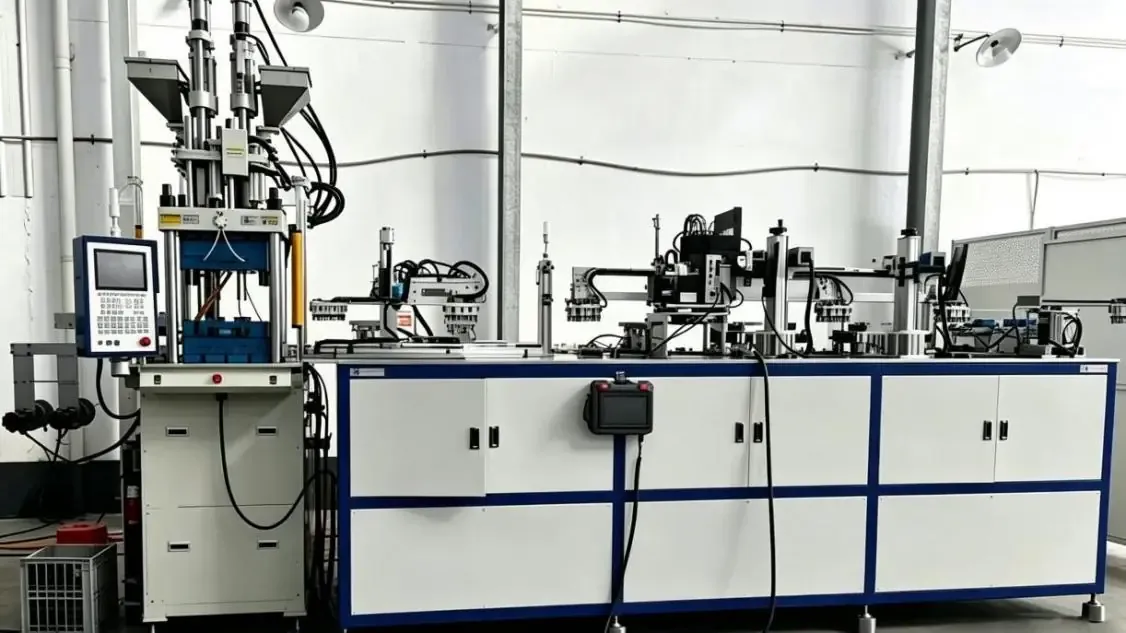
Automating PC Meter Seal Production: Four DA-600DC Cells for an Indian Customer
See how four DA-600DC machines combine PC meter seal molding, robotic handling, labeling and laser processing for an Indian customer's production project.
2026-09-15 | 8 min read | Industry: Electrical and utility security
For an Indian customer producing polycarbonate (PC) electric meter security seals, the project required more than molding small plastic components. Mold loading, part removal, wire handling, labeling and laser processing all had to fit into a coordinated production sequence.
DEBOGE supplied a solution built around four DA-600DC vertical injection molding machines and four matching automation systems, with one dedicated automation system for each machine. Each cell also has one material loader and two dryers. The eight-cavity mold forms the components for four complete seals per cycle, at an approximately 20-second molding cycle.
This case explains the equipment configuration, the handling sequence and the distinction between theoretical molding capacity and actual finished output.
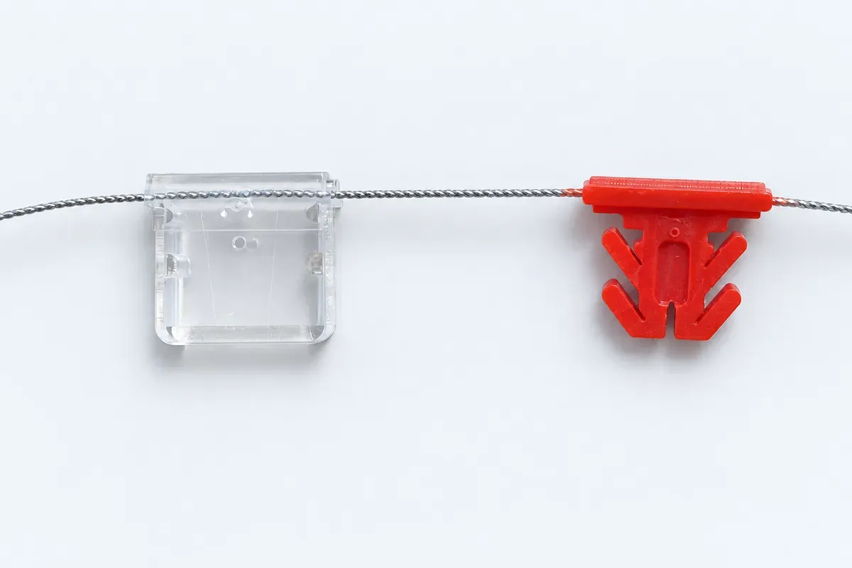
The meter seal product: single-color and two-color options
The sample below shows the seal’s transparent housing and red inner component separated on the steel wire, making the two plastic components visible. DEBOGE machines can produce single-color and two-color meter seal products. The product design, color requirements and mold arrangement should be reviewed together when specifying a production line.
From the product to the production cell
The project combines the molding machine with equipment for handling the molded components and completing the downstream operations.
Project configuration at a glance
The product is a security seal for electric meter and utility applications. The project combines PC molding with the handling and identification operations described below.
| Item | Project configuration |
|---|---|
| Customer location | India |
| Product and material | Electric meter security seal; PC |
| Molding equipment | 4 DA-600DC vertical injection molding machines |
| Automation | 4 dedicated systems, one per molding machine |
| Material loading | 1 loader per machine; 4 loaders in total |
| Material drying | 2 dryers per machine; 8 dryers in total |
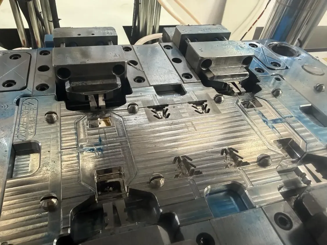
| Mold layout | 8 cavities; two cavities contribute to one complete seal |
| Output per molding cycle | Components for 4 complete seals |
| Molding cycle | Approximately 20 seconds |
| Integrated operations | Robotic mold loading/unloading, wire handling and tensioning, labeling, two laser processing stations, final robotic pickup and discharge |
| Product color capability | Single-color and two-color meter seal production |
Why eight cavities produce four seals per cycle
Cavity count and finished-product count are different in this project. Two cavities are needed to form one complete meter seal, so an eight-cavity mold corresponds to four complete products per cycle. Counting all eight cavities as eight saleable seals would double the capacity estimate incorrectly.
This distinction matters when sizing the automation as well as when calculating output. The handling and subsequent processing stages must accommodate the parts associated with each four-seal batch.
How the molding and automation sequence fits together
The customer required repeated production of small parts with several handling steps after molding. DEBOGE configured each machine with its own automation system to carry the products through those operations.
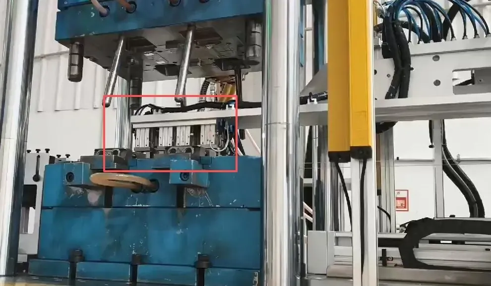
Material preparation and robotic mold access
Material preparation uses the cell’s loader and two dryers. The robotic system then enters the mold area for loading and positioning. The DA-600DC performs the PC molding cycle, after which the automation removes and transfers the molded products.
The machine’s vertical arrangement gives the automation access to the mold area. For this project, machine selection therefore included both the molding requirements and the loading, removal and transfer arrangement. Buyers comparing similar configurations can review the standard vertical injection molding machine structure alongside the automation integration considerations.
Wire handling, labeling and laser processing
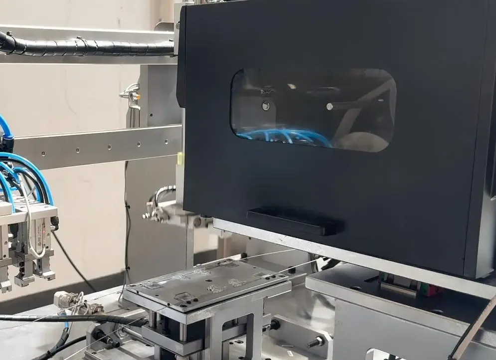
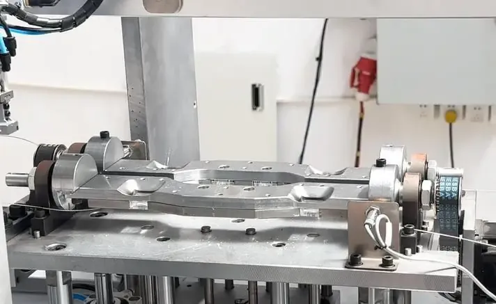
The downstream sequence includes wire handling and tensioning where required, followed by automatic labeling and two laser processing stations. These operations extend the scope of the project beyond the injection machine: product positioning and transfer between stations are part of the production solution.
For a comparable project, the labeling content, laser-processing requirements and part presentation at each station should be defined alongside the mold and molding cycle. Their processing times affect how much finished output the complete cell can sustain.
Final pickup and collection
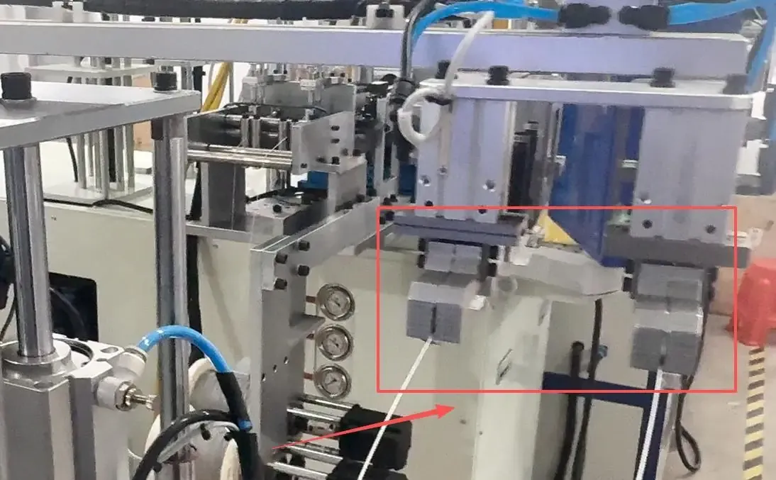
The final robotic unit picks up the processed products and releases them into the collection area. This completes the sequence from material preparation and molding through handling, labeling, laser processing and discharge.
Calculating theoretical output without overstating capacity
Using the project’s approximately 20-second molding cycle and four products per cycle gives the following theoretical molding-based output:
| Calculation | Result |
|---|---|
| Cycles per hour: 3,600 ÷ 20 | 180 cycles |
| Products per machine per hour: 180 × 4 | 720 seals |
| Products per machine per 24 hours: 720 × 24 | 17,280 seals |
| Products across four machines per 24 hours: 17,280 × 4 | 69,120 seals |
These figures assume every machine runs continuously for 24 hours at a 20-second cycle. They are not a measured daily shipment quantity or a guaranteed output. Actual accepted output depends on operating hours, material changes, equipment availability, quality checks, maintenance and the ability of the downstream stations to keep pace.
When planning another line, start with the required quantity of accepted finished products per shift. Then review the molding cycle, transfer sequence and downstream operations together. The distinction between cycle time and loading time is useful when comparing a machine’s molding rhythm with the output of a complete cell.
What the four-cell configuration provides
Dedicated handling equipment supports each machine’s production sequence, while four cells provide the basis for the combined capacity calculation above.
The solution is intended to reduce repetitive manual handling at the integrated steps and make product transfer more repeatable. Its value comes from coordinating those operations with molding and giving each machine a dedicated handling system.
The DA-600DC configuration supports single-color and two-color meter seal production. The required colors and component arrangement should be defined with the product drawings so that the mold and molding configuration match the intended seal design.
Questions to resolve for a similar meter seal project
Does an eight-cavity mold always produce eight finished seals?
No. In this project, two cavities contribute to each complete seal, so the finished-product count is four per cycle. Capacity calculations should use the number of complete products represented by one cycle.
Is 69,120 seals per day the guaranteed output of four machines?
No. It is the theoretical result of four products per 20-second cycle, across four machines running for 24 hours. A production plan must also account for interruptions, quality acceptance and downstream processing.
What auxiliary equipment is included in this project?
Each DA-600DC has one material loader and two dryers. Across the four-machine project, that is four loaders and eight dryers, together with four dedicated automation systems.
What information helps define a new automated seal line?
Prepare the product drawing or sample, PC grade or other intended material, mold layout, finished-product count per cycle, target output per shift and automation requirements. Include the wire-handling sequence, labeling content, laser-processing operations and collection method. Specify whether the product requires single-color or two-color production.
Discuss your product, mold and automation requirements
For meter seals and related electrical components, the machine, mold and handling equipment should be reviewed as a connected production system. DEBOGE can discuss the molding configuration, material loading and drying equipment, robotic handling and downstream operations for your product.
Use the automation-ready machine selection guide to prepare the project information, or send your product and production requirements to DEBOGE engineering.
Related Reading
Have a similar application?
Contact Deboge engineering to discuss your production requirements and machine configuration.